Geogebra Demo: https://www.geogebra.org/calculator/vapprkva
Github Repository: https://github.com/mbird1258/Robotic-Arm-Inverse-Kinematics/
Introduction
This blog post is about figuring out the inverse kinematics behind finding the angles required for each of the 6 axes of a 6 axis robotic arm.
I used cartesian coordinates, with the origin at the center of the base of the robotic arm and the positive y-axis as the front of the robotic arm, for the math. The first axis is the base axis, rotating in the yaw direction like a lazy susan. The second and third axes rotate in the pitch direction. These three axes give us control over the translation of our end point. The second and third axes allow the arm to reach a large circular range of positions in a 2d plane, while the first axis converts this into a sphere in 3d space.
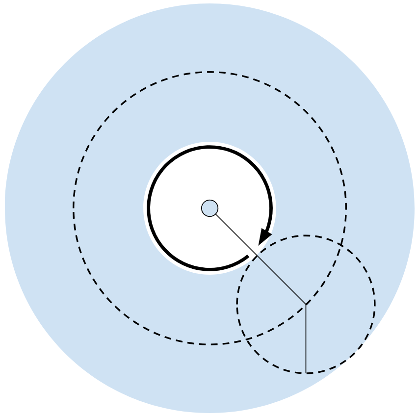
Coverage provided by second and third axes
The fourth, fifth, and sixth axes are dedicated to controlling the orientation of the robotic arm holder, and are pitch, yaw, and roll respectively. I chose this order of orientations because setting pitch to the fourth axis allows us to completely ignore the orientation of the third axis, setting roll to the last axis allows us to completely ignore it as it doesn’t change anything, and the fifth axis is left with yaw.
Calculations
Axes 4, 5, and 6
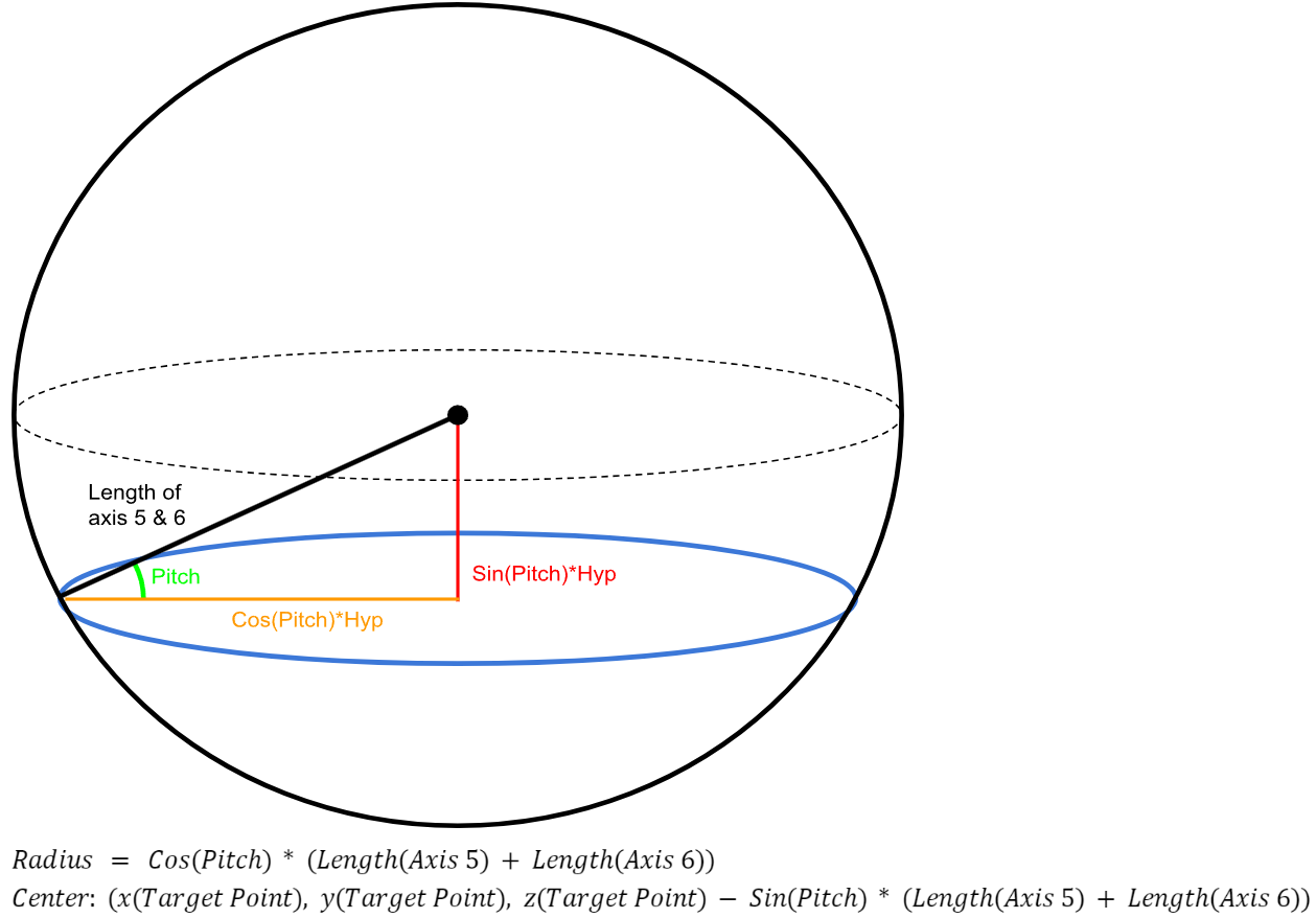
The pitch of the axes 4, 5 and 6 has to equal the pitch of axis 4 as the pitch of axis 4 carries over to axes 5 and 6. Because we know the pitch of the axes 5 and 6, we can limit the potential positions at which the point can exist to a circle. (visual)
To find the radius of the circle and the position of the circle, we first find out how far away from the target point the point can be horizontally and vertically. By constructing a right angle triangle as shown below, we can find out the horizontal and vertical distance of any point from the target point. The radius will equal to the horizontal distance and the position of the center of the circle will equal the Z position of the target point (which is also the center of the sphere) subtracted by/added to the vertical distance.
To find the exact point, we can make use of the desired yaw of the final point and find the corresponding point on the circle as shown below.
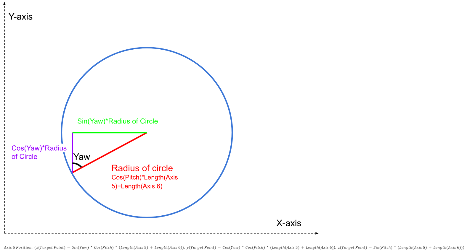
We repeat the same process to get to the point at axis 4, except this time we use the yaw of the first axis.

Axes 1, 2, and 3
To get the yaw value of axis one, since the yaw is transferred to axes 2 and 3, we can just take the arctan of the position of axis 4 to get our yaw.

To get the members of the robotic arm to their correct positions, we need to get the angles ⍺ & β from the image below. Finding the angles directly allows us to avoid directly finding the coordinates of B, saving a lot of time and effort.
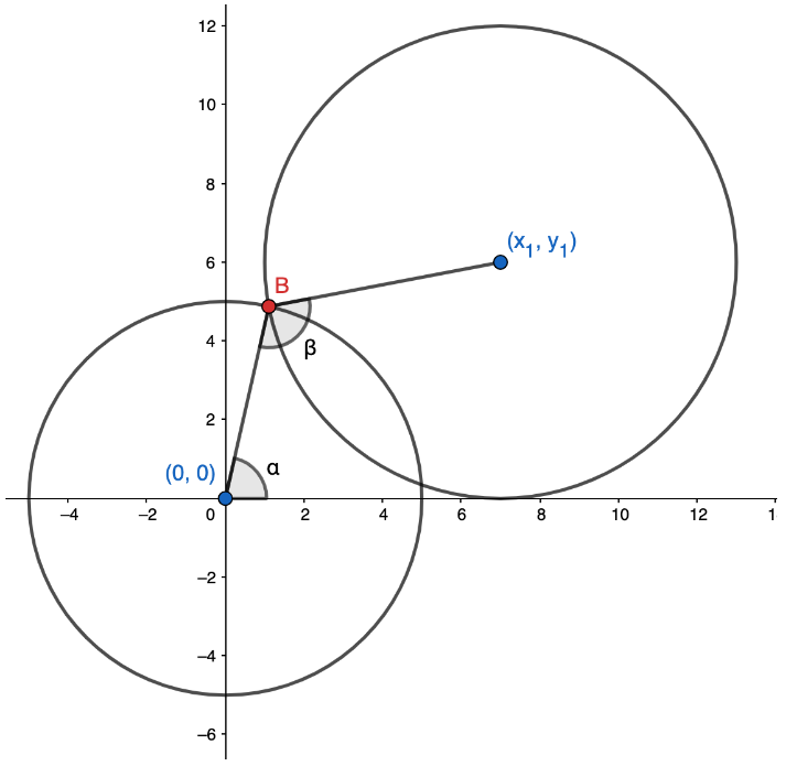
To do so, we can construct a triangle between (0,0), (x1, y1), and B. A quick application of the pythagorean theorem, cosine rule, and tangent function gives us the following values.
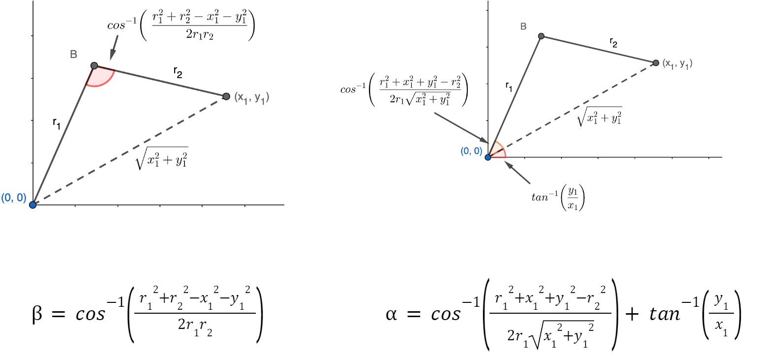
With this, we have all the values we need to provide to the motors in our robotic arm for achieving any position and rotation in 3d space.