Demo Vid: https://www.youtube.com/watch?v=8zoABIoGM0Y
What are Planar Linkages
In the context of Poly Bridge, planar linkages are just a set of rigid members/links connected by nodes constrained to a single plane. This can be thought of somewhat similarly to joints and bones in the body, where links/bones are a fixed length and are connected to each other through nodes/joints and can freely pivot around these nodes/joints. However, in Poly Bridge, these joints and nodes don’t collide with each other as it is all constrained to a single 2d plane.
This set of constraints interested me, since while it seems like a somewhat trivial problem, the only way I really knew to add angles was through a differential drive, which is a somewhat complex 3d construction of gears rotating around each other to add rotation, and would obviously not work in a 2d plane without collision.
Process
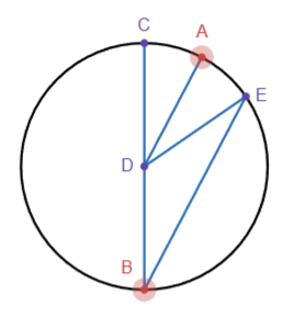
The first step interestingly actually uses the inscribed angle theorem. According to the inscribed angle theorem, angle CDE is double angle CBE. By adding a parallel line to line BE through point D, line DE now rotates at double the speed of line AD. In other words, when we rotate line AD by 0.5 degrees, line DE rotates by 1 degree. However, it is also important to note that DE is effectively a reflection of CD across AD. Thus, if we rotate line BC by -1 degree, line DE rotates by 1 degree. This gives us the ability to rotate DE by rotating either one of two other line segments, AD and BC, which allows us to add their rotations together. Another issue is that line BE is variable in length as E travels along the circle. To fix this, we can use a straight line mechanism such as Hart's A-frame linkage to follow E around the circle.
However, an issue with the current setup is that we are not performing angular addition where A+B=C, but rather 2A-B=C. To fix this, we have to find a way to reduce our input A to 0.5A, and flip B to -B, so that when we feed in our inputs, we get 2(0.5A)-(-B)=C or A+B=C.
Reducing A to 0.5A can be done through the same inscribed angle theorem, fixing line BC, treating DE as the input, and taking AD as the output.
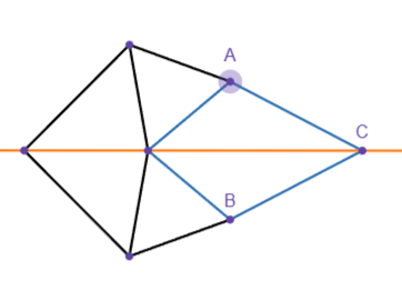
To flip B to -B, however, we need to use a different linkage. By constraining point C to a straight line(orange), when we rotate A, B must rotate in the opposite direction to keep all line segments the same length. However, it is also important to copy this linkage with an angular offset, since when A is on the orange line, the whole linkage will line up and can bind up or start rotating in the same direction instead.
Putting these all together in Poly Bridge gives the following amalgamation, where A is the angle reversing, B is halving the input angle, and C is combining the two with the inscribed angle theorem. While the video shows the output constantly lagging behind what it should be, this is due to the ability for materials in Poly Bridge to stretch and compress slightly, which annoyingly creates a bit of error.