Github Repository: https://github.com/mbird1258/LiDAR-Car/
Premise
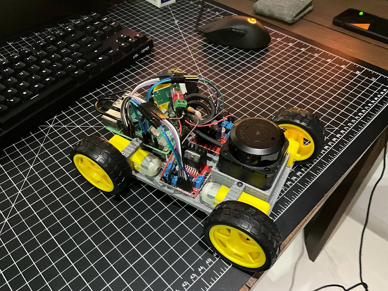
My plan for this project was to create a cheap RC car with a LiDAR sensor attached that can perform basic SLAM(Simultaneous Localization and Mapping), with plans to build off of the project to create a self-driving car.
Software
Odometry
I used odometry to interpolate the position and rotation of the car between the different waypoints of the car to approximate the position and rotation of the car given any time. This is later used to adjust the lidar sensor readings based on the position of the car at the time of the reading, as well as determining what points the car has line of sight of.
The formulas I used were pretty simple, finding the average tangential velocities of the left wheels and right wheels, and then plugging them into the following two equations: RotationalOffset = (v_l*time-v_r*time)/self.WheelRadius ForwardOffset = (v_l*time+v_r*time)/2
Reading from the Lidar Sensor
The process of getting usable data from the lidar sensor was quite troublesome, involving getting the data from the lidar sensor, culling bad points that the lidar sensor returns, converting the data from polar coordinates to cartesian coordinates, and finally adjusting for the movement of the car between the start and end of the lidar scan.
The most time consuming and difficult aspect of using the lidar sensor was getting the data from the lidar sensor in Python, since the software attached to the lidar was written in c++ instead of Python and was not particularly user friendly (here’s the sdk for reference). As a result, I had to convert one of their example c++ code files into a class, and used pybind11 and makefile to painstakingly get the c++ code to compile as a python module. I was especially losing my mind trying to figure out how to use makefiles and pybind11, failing to import the module while receiving no error messages when compiling. Eventually I got it to work with the makefile running the following command:
g++ -O2 -DNDEBUG -I. -I/home/mbird1258/rplidar_sdk/app/pyrplidar/../../sdk/include -I/home/mbird1258/rplidar_sdk/app/pyrplidar/../../sdk/src -I/home/mbird1258/rplidar_sdk/app/pyrplidar -Wall -funsigned-char -fPIC -std=c++11 -fPIC -shared -I/usr/include/python3.11 -I/home/mbird1258/venv/lib/python3.11/site-packages/pybind11/include -I/usr/include/python3.11 -I/usr/include/python3.11 -I. -I/home/mbird1258/rplidar_sdk/app/pyrplidar/../../sdk/include -I/home/mbird1258/rplidar_sdk/app/pyrplidar/../../sdk/src -I/home/mbird1258/rplidar_sdk/app/pyrplidar lidar_driver.cpp rplidar_module.cpp /home/mbird1258/rplidar_sdk/output/Linux/Release/libsl_lidar_sdk.a -o /home/mbird1258/rplidar_sdk/output/Linux/Release/rplidar.cpython-311-aarch64-linux-gnu.so -lrt -L/home/mbird1258/rplidar_sdk/output/Linux/Release -lsl_lidar_sdk -L/usr/lib/python3.11/config-3.11-aarch64-linux-gnu -L/usr/lib/aarch64-linux-gnu -lpython3.11 -ldl -lm -lstdc++ -lpthread -shared -lrt -L/home/mbird1258/rplidar_sdk/output/Linux/Release -lsl_lidar_sdk -L/usr/lib/python3.11/config-3.11-aarch64-linux-gnu -L/usr/lib/aarch64-linux-gnu -lpython3.11 -ld -lm -lstdc++ -lpthread
To cull the bad points from the lidar sensor, I filtered out any points with a quality value below a threshold, and filtered out any points facing backwards. I had to cull the backwards facing points because when I designed my car, I forgot to account for the wires sticking up in the air, so my lidar sensor was too low and its backwards view was obstructed by a bunch of wires. On top of this, I also culled any values that went past one full revolution of the lidar sensor so that, at most, only one full rotation of points would be shown. This was to avoid bad odometry calibration causing a point cloud that appeared smeared due to under or overestimating the movement of the car, making it impossible to fit to the permanent map accurately.
Converting the data from polar coordinates to cartesian coordinates and adjusting for the movement of the car between the start and end of the lidar scan was pretty simple. To do this, I assigned time values to each of the scan values linearly interpolated between the start and end time of the scan, then used the odometry calculations above to determine the position and rotation of the car for each point in the scan. By applying the following two formulas, I converted the polar coordinates to cartesian coordinates while adjusting for the movement of the car:
distance*np.cos(radians+theta)+x, distance*np.sin(radians+theta)+y Distance, Radians = lidar angle x, y, theta = car position & orientation
Communication between car and computer
To communicate between the car and the computer, I used the Python socket library to establish a connection between the two, where each had their own get and send functions to communicate. Additionally, the get function had a blocking parameter, which when false simply returned False if there was no message already in the socket instead of waiting indefinitely.
The data was sent to the car in the format of [flag, opt. arguments]. For example, when [“Get Lidar”] is sent, the car sends back the latest lidar scan, while if [“Drive”, args] is sent, the car updates its driving.
Classification of points
Any point within proximity of a point in the permanent map is classified as a preexisting point, while the rest are considered new points. Pre-existing points are used in the next step to better align the points, while the new points are simply added to the permanent map in a later step.
Reducing error through ICP
I used the iterative closest point algorithm to match our lidar scan’s pre-existing points to the permanent map. Because we’re using the preexisting points only, we don’t have to worry about any points not having a corresponding point in the permanent map. Iterative closest point works by matching each point in the scan to the closest point in the permanent map, then estimating a rotation and translation transformation(to apply to the entire lidar scan preexisting points’ point cloud) that minimises the distance between each pair, repeating this process until the lidar scan and permanent map are as closely aligned as possible. Besides making perfect calibration of the car’s wheel speeds obsolete, this also prevents errors from accumulating over time.
Updating permanently stored map
The map created by the script is stored as a list of points as well as their corresponding confidence values. Then, each time the main loop runs, points in the map near a point from the last scan(i.e. we saw this point just now) have their confidence value increased by one, while points in the map that have no points from the last scan near them and are in the line of sight of the car(i.e. we expected to see this point but didn’t) have their confidence value decreased by one. Then, the points we determined to be new in the classification of points step are added to the map.
Points start with a confidence value of 2 with an upper limit of 10, and if the confidence value drops below 0, the point is removed from the map, which allows the map to update itself when the environment changes while allowing room for error.
Hardware
Materials: 1. Motors + Wheels 2. RPLidar C1 3. Raspberry Pi 4B 4. USB-C PD Trigger Board 5. L298N Motor Driver Controller 6. Jumper Wires
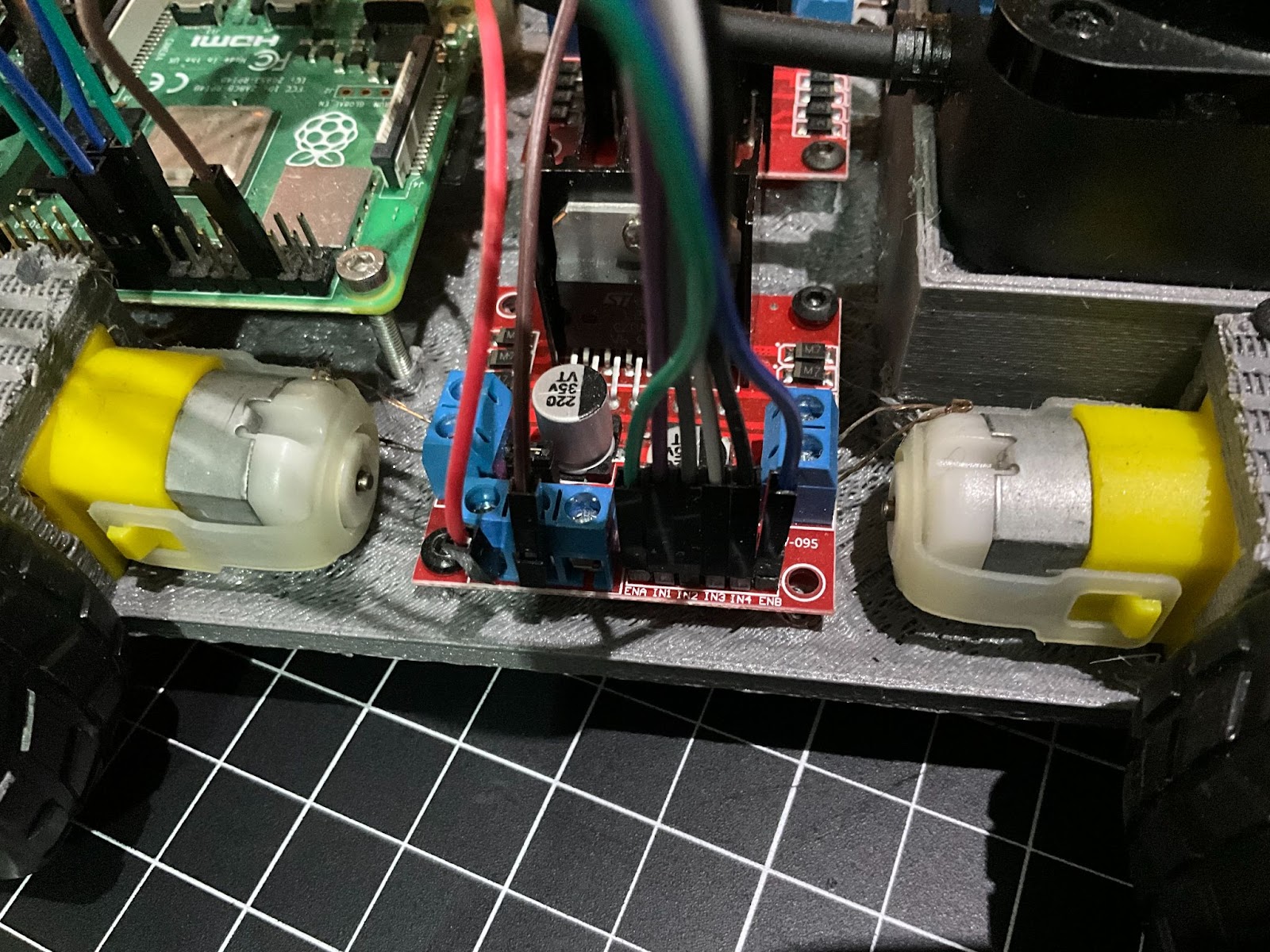
The motors were a bit of a pain to set up. For one, they all seemed to run at different speeds, making it a bit annoying to get the car to drive straight. (In hindsight this might’ve been because I used a single charging cable from a power bank to power 4 motors or my horrific wiring) I also designed the car frame with the pins on the motors facing inwards, where they’re hard to reach, and right next to the motor controllers, making it an absolute pain to wire up. I ended up stripping jumper wires and using the copper wire inside to connect the motors to the motor controllers, which took multiple hours and a lot of pain. On top of everything, to my dismay I found out I couldn’t even get the car to turn. Originally I just assumed that tank steering would work, but I think the wheels had too much friction and thus couldn’t steer, and the motors would also stall if I turned the speed down too low. This also meant I unfortunately couldn’t test if the odometry worked when the car turned.
Besides this, the 3d printing of the car frame itself had plenty of issues. I forgot to add room for a battery to power the car, placed the LiDAR sensor too low preventing it from looking over the wiring behind it, designed the motor mounts poorly making the motors not sit right, and 3d printed with a raft that couldn’t come off, requiring a lot of time to reopen all the screw holds. Overall, I ended up wasting a huge amount of time with issues that could’ve been avoided with a bit more foresight.
The car
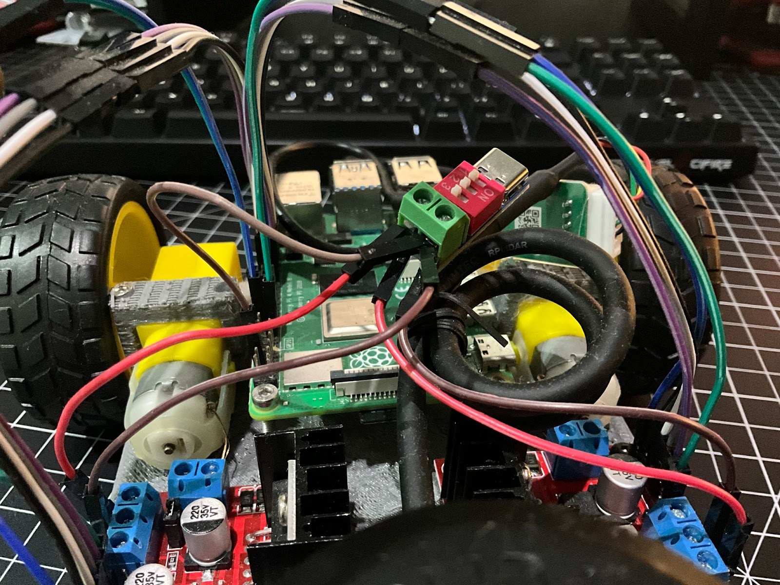
My poor PD board with 5 wires sticking out of it
Motor wiring
Setup Instructions
Recording Movement Data
1. Open DataRepeater1.ipynb 2. Run the first two cells 3. Start up your car or run ‘python3 main.py’ in the terminal if it’s already on 4. The car should start moving forward and sending data back to the computer to be stored in a .pkl file
Testing Code with Pre-Recorded Movement Data
1. Open DataRepeater1.ipynb 2. Run the first and fourth cells 3. Open DataRepeater2.ipynb 4. Run the first cell
Results
Overall, I’m quite happy with the results of the lidar car. The software works as I originally intended, and it seems accurate enough to use as the basis for other projects, even if the project took an extremely long time to finish due to a few dumb mistakes and the lack of software for the lidar sensor. However, the hardware used and the dumb design of my car means that if I were to build off of this project, I’d probably need to completely redo the car, probably using a 2 wheel robot for easier steering and fixing all the other mistakes I made.