Demo Vids: https://youtu.be/QoqZZ-jRLvM
Github Repository: https://github.com/mbird1258/Drone-relative-positioning
Premise
My plan for this project was to determine the relative positioning and orientation of two or more objects with cameras using minimal usage of external libraries. I was inspired to do this by drone shows in HK.
How it works
Overview
The code uses two cameras on the central drone to create a 3d map of features, then the other drones do the reverse from any two points to determine its own position in this 3d map of points.
Feature detection
To detect features, we use the FAST algorithm to detect corners. To improve computation time, we also use some methods to remove ‘low quality’ key points.
The first method, inspired by the SIFT algorithm, is to cull any points that aren’t substantially darker or lighter than the neighborhood. The second method, also inspired by the SIFT algorithm, is to cull any edges, which the FAST algorithm is often susceptible to classifying as corners. We do this by taking three (angle) ranges around the key point centered on the orientation of the key point. For each range, we find the average difference in brightness of the points in the range and the key point. If the value calculated for the central range is too close to either of the outside ranges, then we consider it an edge and cull it.
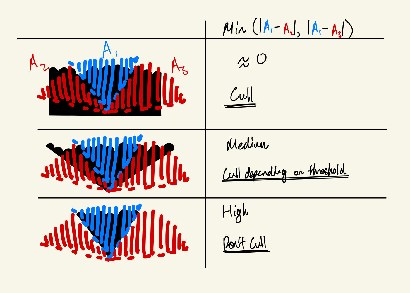
Edge culling algorithm
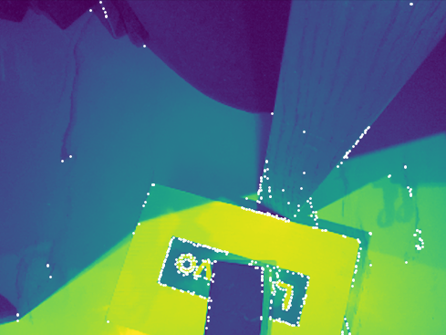
Img after FAST
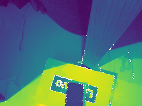
Img after intensity cull
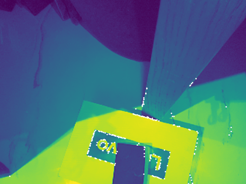
Img after edge cull
With these key points, we calculate descriptors for each of these points that are scale and rotationally invariant and match the points to each other.
My first attempt was to use the following two descriptors for each key point. However, these 3 descriptors alone weren’t enough to reliably match each key point.
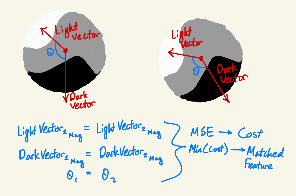
The method that ended up working was a bit more convoluted. First, we find the orientation of the key point through taking all nearby pixels in the point’s neighborhood whose brightness was within a certain range, then taking the average angle of the vectors from the key point to each pixel.
With the orientation, we then split the area around the point into chunks while also taking into account orientation, a method inspired by the SIFT and SURF algorithms. This is also what gives us rotational invariance. Since the rotated points’ coordinates aren’t integers, we use 2d linear interpolation to approximate these values.
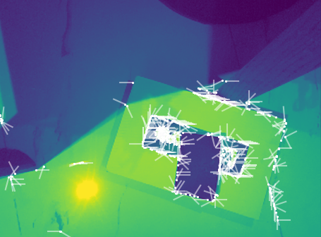
Key point orientations
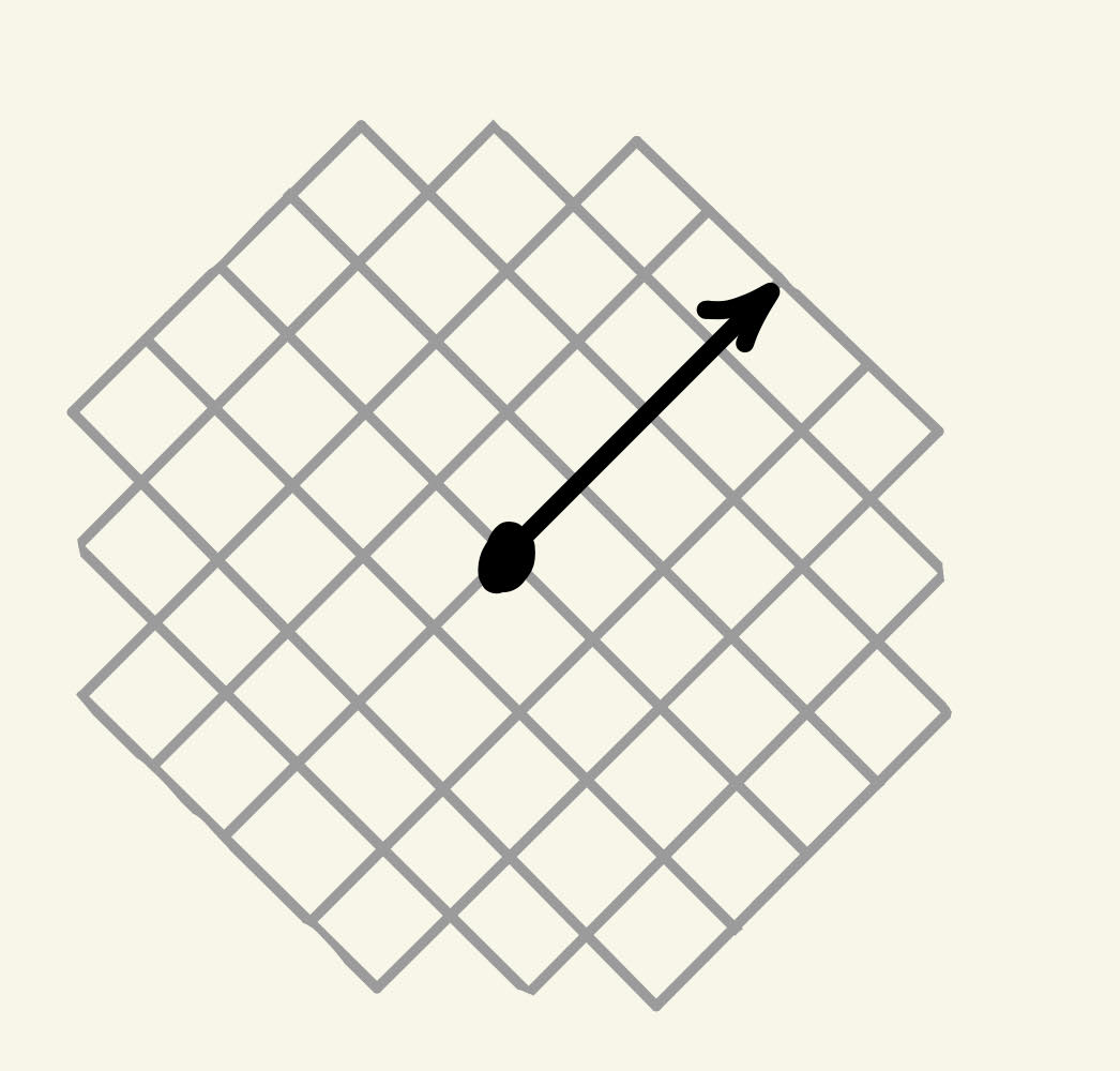
Descriptor chunks
After this, we create a vector for each square subsection in which we average all of the vectors starting from the center of the square to each point, and store the magnitude and direction. We also store the magnitude of the sum of the absolute value of each vector for an extra descriptor.
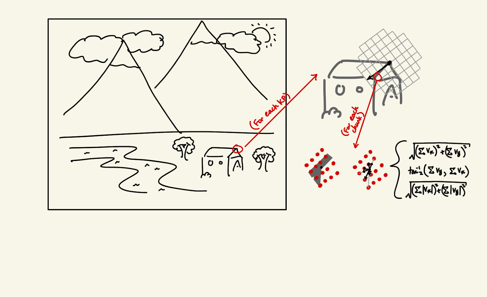
Descriptor calculation
With each key point now assigned a descriptor, we match key points across two images by taking the MSE of each key point in the first image to every other key point in the second image, and iteratively take the minimum value to match key points.
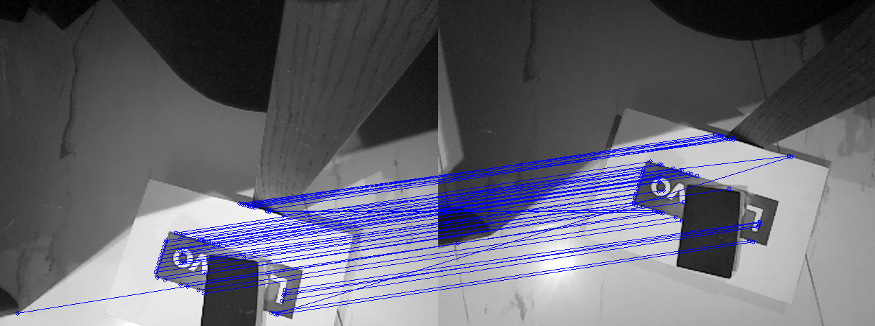
Matched key points
Feature triangulation
To find the 3d position of the features, we draw a line in 3d space from the center of both cameras on the central drone and approximate the intersecting point in 3d space to find the feature’s position in 3d space.
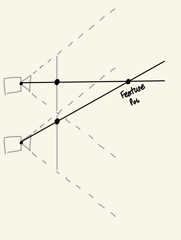
Reverse triangulation
To find the 3d position of a camera from any two features, we use the same method as before, but instead of drawing from the center of both cameras, we anchor the lines on the feature points in 3d space and approximate the intersection to find our camera’s position. We do this for every set of two features and remove outliers to get our final position.
Accounting for orientation
To account for the orientation, we first need to find our orientation. To find pitch and roll, I used an ADXL345 accelerometer.
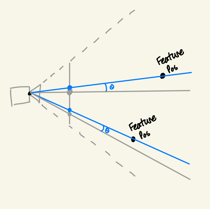
To find the yaw, we take any pair of matched features across two cameras, one from the central drone and another from the second drone. Then, we use the offset in angle of the key points to give us the relative yaw of every drone with respect to the central drone.
To account for yaw, we rotate each key point around the center of the image by the calculated yaw offset.
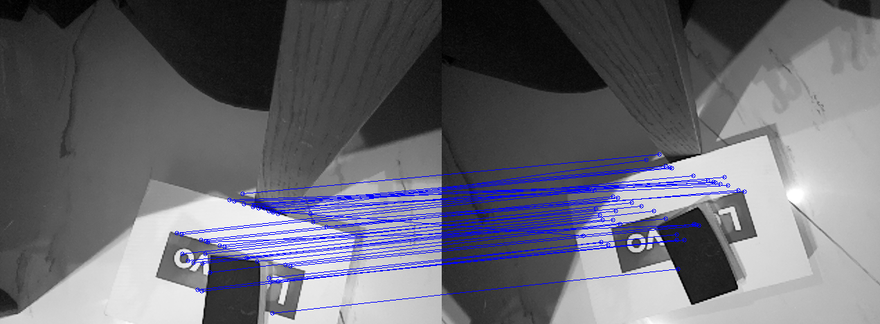
Accounting for yaw (Note that the shape is replicated in the second image)
To account for pitch and roll on the central drone, after triangulating the 3d position of all the features, we then rotate their positions around the origin in accordance with the pitch and yaw to properly account for the pitch and roll.
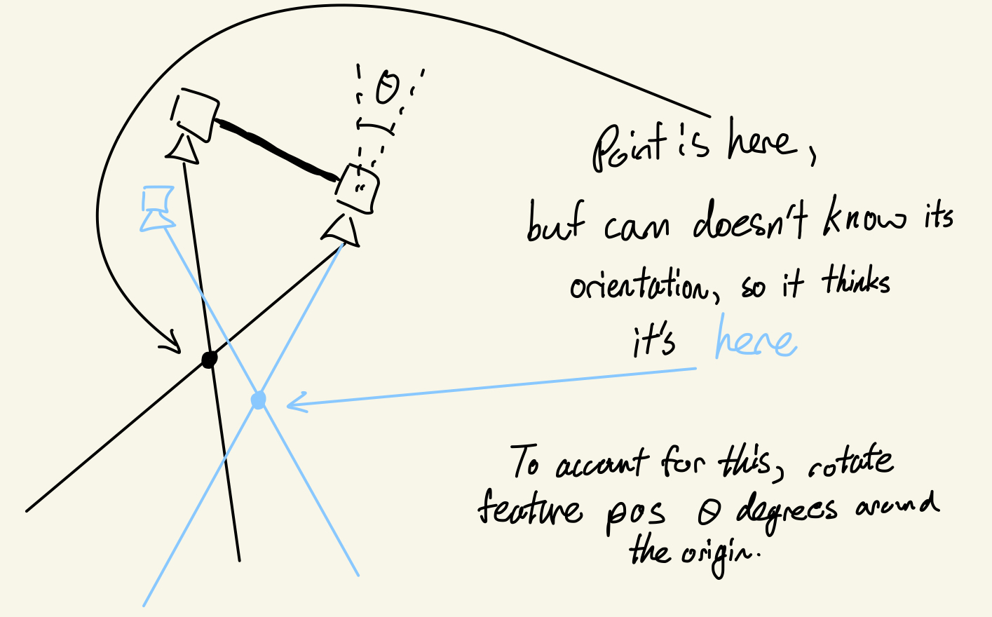
For the secondary drones, we rotate the lines we draw before we reverse triangulate the camera to counteract the pitch and roll of the camera.
Hardware
The full list of hardware used in this project are 3 RasPi 0Ws, 3 RasPi camera modules, 2 accelerometers, 2 power banks, 3 usb to micro usb cables, 3 micro SD cards, and a micro SD to usb adapter.
Full list: - RasPi 0W - RasPi camera module - ADXL345 Accelerometer - Power Bank - MicroUSB Cable - MicroSD - MicroSD Reader
The Raspberry Pis are used with Socket to connect to the computer and send over the camera and accelerometer data. (RasPi setup)
The frames holding it all together are printed from these .STL files(with paper as spacing to keep camera and accelerometer flat and taping the camera lenses to the body as they tend to flop around). I decided against implementing the project on real drones as I would have to make my own to avoid the high costs, they introduce many problems like pid tuning and make iterating take longer and more difficult.
Results
Overall, the project seemed to work pretty well. Compared to other systems, it’s a bit slow and not the most accurate, and it also doesn’t have the greatest tolerance for orientation differences, but I still think it’s quite impressive for its simplicity and cost, as well as the low quality RasPi cameras.
In the future, it could be possible to find the 3d position of more features from any 2 drones so that the range is not limited to the central drone. The current system is also centralized, but it shouldn’t be too hard to fully decentralize it with more powerful raspberry pi computers.